
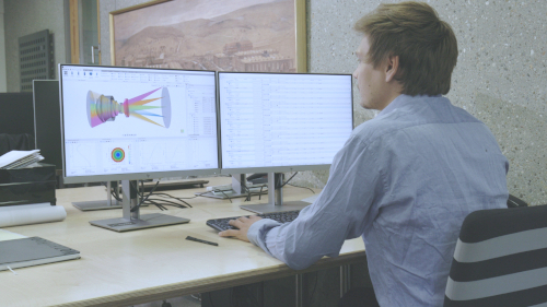


Compensators for the Alignment Process in QUADOA® Optical CAD
Compensators model the alignment steps of an optical system in the tolerance analysis of QUADOA® Optical CAD. Many systems are adjusted during assembly or use, for example by refocusing. Errors that are removed by such an adjustment do not affect the final performance, so a tolerance analysis without compensators is too pessimistic. In QUADOA®, each compensator has its own merit function and variables, and several compensators are applied one after another, just like a multi-step alignment procedure.
Key points
- A compensator has a merit function and its own variables.
- Besides your own merit functions, two defaults exist: Wavefront RMS and Spot Size RMS.
- Several compensators are applied from top to bottom, modeling a multi-step alignment.
- Select the compensator in the drop-down above the Optical Design Editor to set its variables.
- Prepare the model with assemblies and pivot points before tolerancing.
Terms used in this article
- Compensator
- An object that re-optimizes selected variables after the tolerances are applied, to simulate an alignment step.
- Alignment strategy
- The sequence of adjustments made during assembly, such as collimating first and focusing second.
- Shearing interferometer
- An interferometer that checks collimation, used here to align the collimator.
Why use compensators?
Some products, such as smartphone camera lenses, are built so tightly that no alignment is needed. Most other systems are aligned at some point, from the user focusing a camera to multi-step procedures with metrology in production. Tolerances that cause errors removed by these steps do not reduce the final performance. Compensators simulate the alignment, so the tolerance analysis gives a realistic result instead of assuming that all errors stay uncorrected.
Example system and alignment strategy
Light leaves a fiber, is collimated by a collimator assembly and focused by a microscope objective assembly. The alignment has two steps:
- Collimation: the collimator has tilt and decenter tolerances, but its Z position is aligned with a shearing interferometer, very accurately, until the wavefront is collimated and the defocus is gone.
- Focus: the objective is mounted in front of the collimator with position tolerances; only the defocus is then adjusted.
For simplicity, only the tolerances of the two assemblies are considered, not those of the single lenses inside them.
Step 1: Prepare the model
- Group the elements into assemblies: here the collimator and the objective.
- Set the pivot points of the assemblies at their mounting points, so a tilt rotates the objective around the point where it is mounted, not around its center.
These two steps should always be done before a tolerance analysis.
Step 2: Define the tolerances by hand
With only two tolerance sets, adding them by hand is easier than using the wizard:
- Add an Element tolerance container and assign it to the collimator doublet with ID
Colli. Keep only Position (XYZ) and Angle (tilt XY); delete Thickness and Index. - Add an Assembly tolerance container for the objective with ID
Assembly Objective, with Position and Angle.
Step 3: Set up the compensators
Two additional merit functions are prepared: one minimizes the defocus of an extra sequence (sequence 2, blue) that checks the collimation, the other minimizes the spot radius in the image.
- Add a Compensator in the Tolerancing tab and assign the merit function Defocus Collimator.
- Select Compensator 1 in the drop-down above the Optical Design Editor and make the Z position of the collimator doublet variable.
- Add a second compensator with the merit function Spot Image.
- Select Compensator 2 and make the Z position of the image surface variable.
Compensators are applied in their order from top to bottom: first the collimation, then the focus. Adjustments done in one step can share one compensator. Instead of your own merit function, a compensator can use the defaults Wavefront RMS or Spot Size RMS with a selected sequence.
For every perturbed system, QUADOA® first applies the tolerances, then runs the compensators one after another, optimizing their variables with their merit functions, and finally evaluates the performance merit function.
Step 4: Run the tolerance analysis
- Sensitivity analysis with the main merit function as performance criterion: the Z-position tolerances of the collimator and the objective assembly drop to almost zero impact, because they are compensated.
- Monte Carlo simulation with 100 systems: the distribution of the performance includes the compensation.
The model files of this tutorial are linked in the description of the video on YouTube. See sensitivity analysis and Monte Carlo simulation for the analyses themselves.
Video tutorial: compensators for alignment
This 9-minute video models a two-step alignment of a fiber collimator and a microscope objective with compensators.
Video length: 8:45 min · Also on YouTube: Compensators: Modeling Alignment Steps in Tolerancing with QUADOA® Optical CAD
Frequently asked questions
A compensator re-optimizes selected variables after the tolerances have been applied, to simulate an alignment step such as refocusing. Errors that it removes do not reduce the evaluated performance.
Add one compensator per step, each with its own merit function and variables. Compensators are applied from top to bottom in the list.
Select the compensator in the drop-down menu above the Optical Design Editor, then activate the variables, for example a Z position.
No. Besides your own merit functions, you can use the defaults Wavefront RMS or Spot Size RMS together with a sequence.
Group the elements into assemblies as they are mounted, and set the pivot points at the mounting points, so tolerances act like real mechanical errors.