
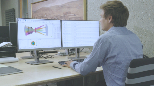


Pivot Points for Lenses and Assemblies in QUADOA® Optical CAD
A pivot point in QUADOA® Optical CAD defines the point an element or assembly rotates around. By placing it where the real mount lets the part tilt, for example at the lens center, an edge or the center of curvature of another lens, the model follows the mechanical dependencies of the real system. This makes tolerance analysis more realistic and takes only a few minutes to set up.
Key points
- Pivot points can be set for single elements, whole assemblies and elements inside assemblies.
- They are entered in the off-axis parameters of the element in the Optical Design Editor.
- The pivot point is given as x, y, z coordinates.
- Typical choices: the element’s own center, a corner of the lens, or the center of curvature of another lens.
- A slider parameter for the rotation makes the effect easy to check.
Terms used in this article
- Pivot point
- The point around which an element or assembly rotates.
- Mechanical dependency
- The way elements move together because of how they are mounted.
- Center of curvature
- The center of the sphere that a spherical surface is part of.
Why do pivot points matter for tolerancing?
A tilted lens does not rotate around an arbitrary point: it rotates around the point defined by its mount. Thanks to the high-level element structure of QUADOA®, these mechanical dependencies of elements and assemblies can be modeled just like in the real system. Tolerance analyses then tilt each part around the correct point, which gives more realistic results.
How to set a pivot point
- In the Optical Design Editor, click the element or assembly.
- Click the off-axis arrow to show the off-axis parameters (see Optical Design Editor filters).
- Scroll to the right to the pivot point options.
- Enter the coordinates in Pivot X, Pivot Y and Pivot Z, for example x = 0, y = 0, z = 2.5. They are measured relative to the origin of the element; the default (0, 0, 0) is the element’s own origin.
- To check it, enter a slider parameter for the rotation about X and move the slider.
Examples of pivot points
The model in the video has five pivot points. Three lenses are assumed to be mounted together and are therefore placed in a common assembly.
| Element | Pivot point | Rotates around |
|---|---|---|
| Lens 1 | x = 0, y = 0, z = 2.5 | Its own center |
| Lens 2 | x = 0, y = 0, z = 1.7 | The upper right corner of the lens |
| Lens 3 | Center of curvature of the first lens | The center of curvature of lens 1 |
| Assembly | Center of the assembly | Its own center, with all lenses inside |
| Lens inside the assembly | x = 5, y = 5, z = 5 | Its own pivot point, independent of the assembly |
Pivot point and order of position and rotation
How the pivot point acts depends on the Pos/Rot Order of the element:
- Pos first: the element is moved first and then rotated around the pivot point, measured from its new origin.
- Rot first: the element is rotated first; the translation is then applied in the rotated coordinate system.
- Z Pos XY: the element is moved along Z, rotated around the pivot point, and then decentered in X and Y.
Note: The pivot point can be changed later without moving the element, but not while its position or rotation depends on a slider or multi-config parameter. Replace the parameter with a number before converting.
The pivot point can be changed later without moving the element; see converting positions and dependencies.
Video tutorial: pivot points
This 3-minute video shows five pivot points on lenses and an assembly, each animated with a slider.
Video length: 3:27 min · Also on YouTube: Pivot Point in QUADOA® Optical CAD
Frequently asked questions
The point around which an element or assembly rotates. It models how a part tilts in its real mount.
In the Optical Design Editor, open the off-axis parameters of the element or assembly with the off-axis arrow and enter the pivot point coordinates.
Yes. The assembly can rotate around its own pivot point, and each element inside it can have its own pivot point as well.
A tilt tolerance rotates the element around its pivot point. If the pivot point matches the real mount, the tolerance analysis reflects the real mechanical behavior.
(0, 0, 0), the origin of the element’s own coordinate system. Pivot X, Y and Z are always measured relative to this origin.