Welcome to the QUADOA® Media CenterDiscover the newest videos, tutorials, articles, and brochures, all in one place. Stay updated with the latest insights and resources tailored to your needs. YouTube channel
Welcome to the QUADOA® Media Center! These video tutorials and resources are designed to help you quickly learn the basics of QUADOA®,
allowing you to start using the optical design software for basic workflows within just a few hours.
Whether you're new to optical design or looking to sharpen your skills, our videos will guide you step-by-step.
Additionally, you can discover the newest QUADOA® videos, tutorials, articles, and brochures - all in one place.
Stay updated with the latest insights and resources tailored specifically to your needs. Dive in and start mastering QUADOA® today!
1. Basics
1.1 BASICSLens ConstructionIn this video tutorial, a simple singlet lens is created using the Lens Wizard and the construction of the lens is explained in the Optical Design Editor.
Video Length: 2:18 min
1.2 BASICSRaytracingIn this video tutorial, a light sequence is traced through a singlet lens by adding a source and an imaging surface. In addition the autosequence is explained.
Video Length: 3:08 min
1.3 BASICSEnhance Computing and GUI PerformanceIn this video tutorial it is explained how to enhance the computational performance to increase the computing speed and to accelerate the graphical user interface.
Video Length: 4:15 min
1.4 BASICSRecord VideoThis video shows how to record a video of the optical system directly inside QUADOA® and how to set up the camera movement.
Video Length: 3:03 min
1.5 BASICSFilters for Optical Design EditorIn this video tutorial, we walk through the various filters available in the Optical Design Editor (ODE).
Located at the top of the ODE, these filters allow you to streamline your workflow by hiding elements that aren't relevant to your current project.
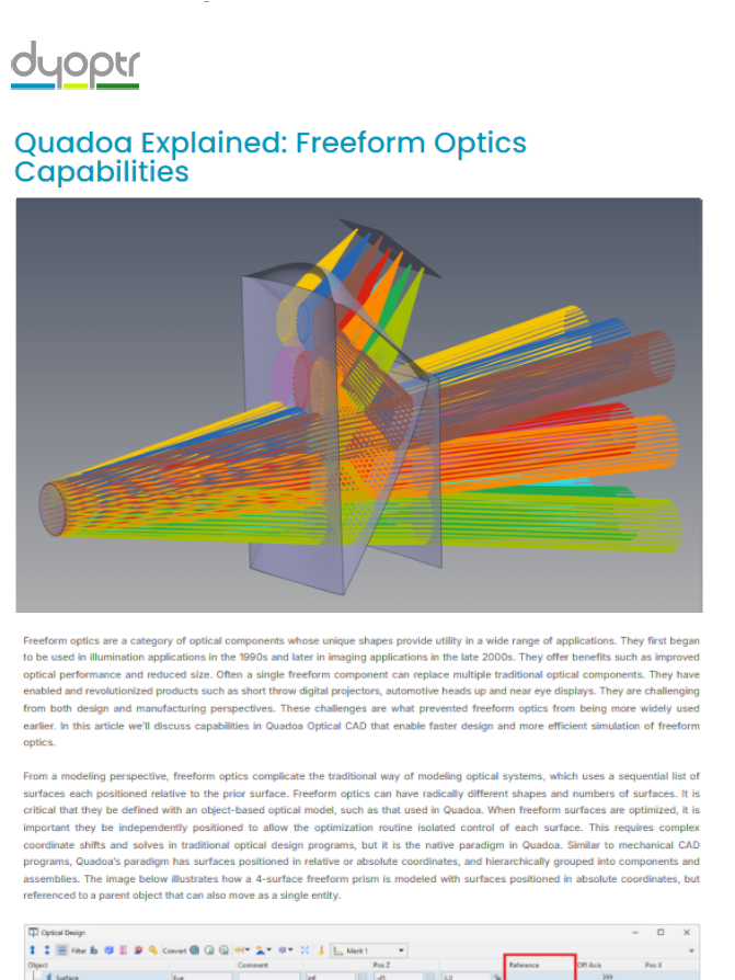
2.1 CONSTRUCTIONFreeform & Stack DefinitonIn this video tutorial we learn how to create freeforms by adding different shapes to a lens (e.g. aspheres, Gauss peak, cosine structure). With the stack definition, any number of shapes can be combined with each other, which gives maximum flexibility with regard to the shape definition of a lens surface.
Video Length: 3:37 min
2.2 CONSTRUCTIONAssemblyIn this video tutorial multiple lenses are assigned to a common assembly. An assembly has its own coordinate system which allows to position, move or rotate all elements in the assembly, such as lenses or surfaces, together. In addition a tolerance analysis can be performed for a single assembly, which enables a very realistic tolerance analysis of the optical system.
Video Length: 2:22 min
2.3 CONSTRUCTIONGlobal & Local Coordinate SystemIn this video the difference between a local and a global coordinate system is explained.
Video Length: 1:30 min
2.4 CONSTRUCTIONAbsolute & Relative PositionsThis video tutorial explains the absolute or relative positioning of elements within a coordinate system. Relative positions relate to the position of the last surface of the previous element, whereby an absolute positioning is referring to the absolute value in the coordinate system.
Video Length: 2:23 min
2.5 CONSTRUCTIONLens CatalogThis video tutorial explains how to insert lenses out of the lens catalog and how to filter the catalog by different filters.
Video Length: 1:47 min
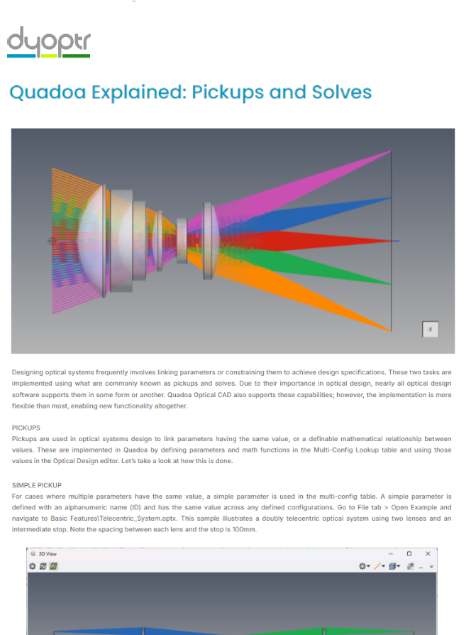
2.6 CONSTRUCTIONMulticonfig Lookup Table & Parameter (Replacement for Pickups)This video tutorial explains how to insert parameters instead of numerical values by using the Multiconfig Lookup Table.
Video Length: 3:25 min
2.7 CONSTRUCTIONSlider Interface & ParameterIn this video the Slider Interface is explained. With the Slider Interface parameters can be defined by a minium and a maximum value. The Slider enables a sliding between these values.
Video Length: 3:29 min
2.8 CONSTRUCTION3D-View EditorThis video explains how to work on lens and surface parameters and how to select single rays and get all the ray data directly inside the 3D-View without having to switch to the Optical Design Editor.
Video Length: 5:44 min
2.9 CONSTRUCTIONConvert Surface Form WizardIn this tutorial I will show you how to convert a form description of an Asphere into the form description of a Qbfs Q-Type-Asphere without changing the shape of the form and without changing the optical system.
Video Length: 3:00 min
2.10 CONSTRUCTIONAdding Measurement/Simulation Data to SurfaceIn this tutorial I will show you how to add data from measurements or from simulations as for example from mechanical FEM simulations to a surface.
Video Length: 2:04 min
2.11 CONSTRUCTIONPivot PointBy setting up Pivot Points for single elements and whole assemblies, it is possible to model and simulate the mechanical dependencies for the tolerance analysis in a very intuitive way, leading to realistic simulation and tolerancing.
Video Length: 3:26 min
2.12 CONSTRUCTIONConvert Positions & DependenciesIn this video it is described how to convert positions and dependencies of elements to each other, even after finishing the complete design, without affecting and changing the optical elements. This is of great importance for accurate and realistic tolerance results.
Video Length: 3:03 min
2.13 CONSTRUCTIONGRIN Material PropertyThis video explains how GRIN material properties can be used to simulate traditional GRIN lenses, manage index inhomogeneities for tolerancing, and address thermal lensing in high-power laser systems.
2.14 CONSTRUCTIONFloating AperturesThis video explains the different settings and definitions of floating apertures and shows how lens edges can be defined.
2.15 CONSTRUCTIONChamfers and FlangesThis tutorial shows how to define and add more complex lens edge geometries, such as chamfers and flanges, to an optical design.
3.1 RAYTRACINGAuto SequenceThe default Auto Sequence is explained in this video tutorial. It shows how the Auto Sequence is defined and how rays can be traced through a system that consists of several lenses.
Video Length: 2:19 min
3.2 RAYTRACINGRay Tracing and Sequence SettingsThis video explains step-by-step the different ray tracing and sequence settings in QUADOA®. Essential elements such as source type selection, wavelength configuration, field settings, and more advanced options like apodization and polarization states are discussed.
Video Length: 3:01 min
3.3 RAYTRACINGUser SequenceThe User Sequence is explained in this video tutorial. With a User Sequence the sequential paths through a system can be defined completely invdividual. This makes it very easy to simulate systems with multiple sequential paths, such as interferometers, or to perform sequential reflex analyzes.
Video Length: 3:14 min
3.4 RAYTRACINGGhost ReflexThis video tutorial explains how ghost reflexes can be generated and how the reflexes can be analyzed individually. Furthermore, it is shown how the ghost reflexes can be sorted according to the maximum illuminance or the maximum total flux in order to easily identify the most problematic reflexes.
Video Length: 4:31 min
3.5 RAYTRACINGGhost Reflex AnalysisIn this video the intensity of the ghost reflexes and the distribution of the ghosts on the imaging surface will be analysed.
Video Length: 3:24 min
4. Polarization
4.1 POLARIZATIONPolarized Light SourceThis video describes how to set up a polarized Light Source (e.g. Circular Polarization or Jones Complex) and how to define the Polarization Settings in the Source.
Video Length: 2:45 min
4.2 POLARIZATIONPolarization ElementsIn this video it is shown how to add Polarization ELements as a Quarter Wave Plate or a Jones Matrix to a Lens Surface.
Video Length: 3:09 min
4.3 POLARIZATIONPolarization Capabilities of QUADOA® Optical CADThis presentation will give an overview of state of the art polarization features as well as some newly introduced unique features.Covered topics are:
- Jones / Müller calculus and its limitations in describing real world polarization effects
- Polarization analysis features
- Birefringent ray tracing for bulk materials as well as birefringent thin film coatings
Video Length: 25:39 min
5. Mechanics
5.1 MECHANICSImport Mechanics & Intersection AnalysisIn this video mechanical elements are imported to the optical system. Furthermore it will be analysed if there is an intersection between the optical rays and the mechanical parts.
Video Length: 2:53 min
6. Analysis
6.1 ANALYSISBasic Plot SettingsThis video describes how the Analysis Plots can be set up and how settings can be changed.
Video Length: 1:46 min
7. Optimization
7.1 OPTIMIZATIONSpot Radius OptimizationIn this video the spot radius of an optimization of an achromatic doublet is shown. The Merit Function is defined with different Optimization Goals/Targets and in addition it is shown how to set up Lagrange constraints.
Video Length: 4:35 min
7.2 OPTIMIZATIONMaterial SubstitutionIn this video it is described, how to substitute Materials by using the Extended Optimization.
Video Length: 2:29 min
7.3 OPTIMIZATIONMath ExpressionIn this video tutorial it is described how to use a math expression for the optimization. It is also shown how to perform a computation in the math expression with different variables or tracing targets.
Video Length: 2:08 min
7.4 OPTIMIZATIONMaterial and Substitute CatalogThis video tutorial shows how to create a user defined materials catalog and how to set up a substitute materials catalog. Substutite materials can be used by the optimizer to optimize materials.
Video Length: 2:55 min
7.5 OPTIMIZATIONMultiple Merit Function OptimizationIn this tutorial multiple merit functions and multiple sequences are used to optimize an optical system. Using multiple merit functions is of great advantage e.g. for complex systems with several assemblies and multiple ray paths. Further multiple merit functions can be used for Tolerancing to evaluate the optical performance and for setting up compensators.
Video Length: 5:28 min
7.6 OPTIMIZATIONComputer Generated Hologram (CGH) OptimizationOptimization of a computer generated hologram (CGH) for the interferometric testing of aspheres. This tutorial shows how to optimize the phase function of a CGH with source type "From Surface" that emits rays perpendicular to the aspheric surface.
Video Length: 7:01 min
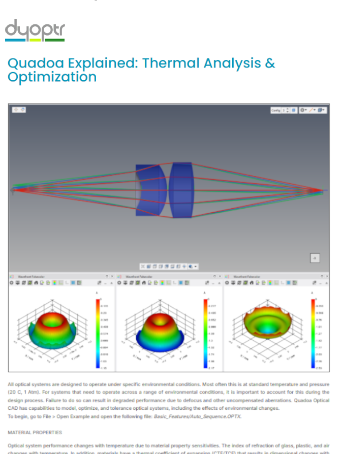
7.6 OPTIMIZATIONThermal AnalysisIn this tutorial, a complete first-order thermal analysis in Quadoa is demonstrated using a beam expander design. The goal is to optimize the wavefront error so the system performs reliably across a temperature range from -20°C to +80°C, while accounting for all major thermal effects, including asphere expansion, temperature-dependent refractive index changes, and mechanical expansion of the mounting.
8.1 TOLERANCINGDefine TolerancesThis video describes how to set up a Tolerance Analysis and how to define Global & Specific Tolerances for single elements.
Video Length: 3:46 min
8.2 TOLERANCINGSensitivity Analysis & Monte Carlo SimulationIn this video a Sensitivity Analysis and a Monte Carlo Simulation is performed. In addition it is described how the tolerances have an impact on the Merit Function.
Video Length: 2:37 min
8.3 TOLERANCINGCompensators for alignment processThis tutorial demonstrates how to perform a tolerance analysis for systems, where one or more manual alignment steps are included during the assembly process of the optical system. The tutorial shows how to set up the compensators that simulate the alignment strategy step by step based on a simple example.
Video Length: 8:43 min
9. Scripting
9.1 SCRIPTINGPython InterfaceThis video explains the basics of the Python Scripting Interface and shows how to use the Python Wizard to create a PSF Plot and a Spot Diagram.
Video Length: 2:57 min
Design Examples
VideoDesign of a parametric off-axis mirror telescope with QUADOA® Optical CADThis tutorial demonstrates how to design a parametric off-axis mirror telescope in QUADOA® step by step in only 13:37 minutes. The tutorial includes the definition of the surface shapes and apertures, setting up lookup parameters, defining the sequential raytrace, optimizing the design and analyzing the image quality. In a final step the mirror-surfaces are converted to volumetric elements for CAD export.
Video Length: 13:37 min
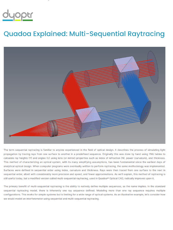
VideoHead-Up-Display (HUD) design: The advantage of the multi-sequential raytracing capabilityThe 20 min video tutorial covers all steps from importing the windshield from mechanical CAD, setting up the driver's eyebox and virtual image, importing the mechanical building area, and actually optimizing the free-form surface. The image quality and the impact of sunlight will further be analyzed directly in the same model by taking advantage of QUADOA®'s unique multi-sequential raytracing capabilities.
Video Length: 20:58 min
VideoCooke Triplet Lens Design with QUADOA® Optical CADThis tutorial demonstrates how to design and optimize a lens in QUADOA® using a classic Cooke triplet as an example.
The design process starts with an empty file from scratch and goes through the design process step by step, from the set up of the start system through the optimization up to the fine tuning of the final lens design.
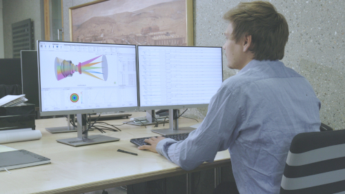
VideoWhat is QUADOA® Optical CAD?See how QUADOA® Optical CAD can enhance your optical design process and how QUADOA®'s design features can facilitate your workflow.
Video Length: 3:51 min
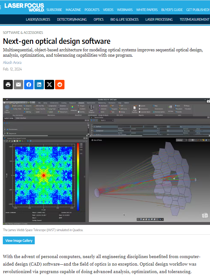
VideoSimulation of the alignment of the primary mirror segments of the JWSTIn QUADOA®, the model is built using the compound surface that can be used to design "faceted" optical systems like the JWST.
Video Length: 0:16 min
VideoBuilding of Fizeau InterferometerSee the workflow of buiding up a Fizeau Interferometer in QUADOA® Optical CAD.
Video Length: 15:03 min
VideoOpto-mechanical lens group mounted on an oscillating poleFor the accurate tolerancing of an optical system besides the optics
itself the modeling of the mechanics plays an important role. For example, the
mechanics may influence the pivot point of a rotation or affect how lenses
inside an assembly tilt and translate individually and as a group. The
assembly item in QUADOA® can not only contain optical but also mechanical elements.
This enables a straight forward modeling of an opto-mechanical system by directly
copying the real-world structure.
Video Length: 0:20 min
VideoSequential Real-Time Ghost Analysis of a camera lensThe Multi-Sequential Raytracing capability of QUADOA® provides a huge advantage, through its application for sequential
ghost analysis. QUADOA®'s Ghost Wizard allows to easily generate any relevant ghost sequences. The 3D View can visualize
the ghost rays directly inside the model. The ghost analysis features allow to quickly identify critical surfaces and to
use the information to optimize for a better stray light performance. Compared to non-sequential raytracing, a huge gain
in raytracing speed can be achieved allowing to simulate more rays in a shorter amount of time.
Video Length: 0:20 min
TalkUsing QUADOA® Optical CAD for the simulation of form-measuring interferometers and other optical metrological instruments
Video Length: 18:34 min
TalkPolarization Capabilities of QUADOA® Optical CADThis presentation will give an overview of state of the art polarization features as well as some newly introduced unique features.Covered topics are:
- Jones / Müller calculus and its limitations in describing real world polarization effects
- Polarization analysis features
- Birefringent ray tracing for bulk materials as well as birefringent thin film coatings
Video Length: 25:39 min
Webinars
Live Webinar July 31, 2024Intro to QUADOA® Optical CADThis webinar shows the key features and comprehensive capabilities of QUADOA® Optical CAD.
Gain valuable insights and see how QUADOA® can elevate your optical design projects.The speaker Akash Arora worked for over 9 years at Zemax and went on to engineer augmented reality systems for Huawei and Microsoft.
He has used every major optical design software package on the market and has experience as both a provider and customer of optical
design software.
CAD-Based Optical Design with Quadoa (Series in Optics and Optoelectronics) Author: Rafael G. González-Acuña, senior lens designer at Huawei Technologies, Publisher: CRC Press