
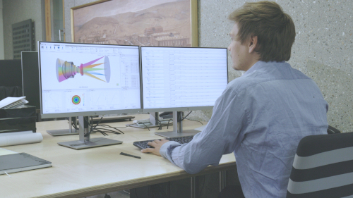


How to Use Assemblies in QUADOA® Optical CAD
An assembly in QUADOA® Optical CAD groups several elements under one common coordinate system. Moving or rotating the assembly moves and rotates all elements inside it together. This simplifies complex folded and off-axis systems, and it allows each assembly to be toleranced separately, just as it will be mounted in production.
Key points
- Each assembly has its own coordinate system.
- All elements in an assembly move and rotate together.
- Assemblies simplify folded and off-axis systems.
- Each assembly can be toleranced separately, for more realistic tolerancing.
- Add an assembly from the Construction tab or with right-click → Add Assembly, then drag elements into it.
Terms used in this article
- Assembly
- A group of elements with a common coordinate system.
- Assembly coordinate system
- The local coordinate system of the assembly, to which the positions of its elements refer.
- Tolerance analysis
- An analysis of how manufacturing and mounting errors affect the performance.
Why use assemblies?
- Common coordinate system: all elements inside an assembly can be moved together through the assembly’s own coordinate system. This is especially useful for off-axis and folded systems, where several elements are folded or moved as a group.
- Realistic tolerancing: when lenses are grouped into assemblies, each assembly can be toleranced separately, reflecting how the system will be built in production.
How to create an assembly
- In the Construction tab, click Assembly, or right-click in the Optical Design Editor and choose Add Assembly.
- Drag and drop the lenses into the assembly.
- Click the assembly: all lenses that belong to it are highlighted in the 3D view.
How to move and rotate an assembly
Change the position or rotation of the assembly itself:
- Set the position Z of the assembly to, for example, 20 mm: all lenses move by 20 mm.
- Set a rotation of, for example, 20°: all lenses rotate together with the assembly.
Assemblies can be nested: an assembly may contain sub-assemblies, so you can model the mechanical hierarchy of the real instrument. When an assembly is selected while you add a new element, for example a lens from a wizard or the lens catalog, the element is inserted directly into that assembly.
For tolerancing, assemblies have their own position and angle tolerances, defined either globally or for one assembly by its identifier.
The positions of the lenses inside the assembly refer to the assembly coordinate system; see global and local coordinate systems. To define the point an assembly rotates around, use a pivot point.
Video tutorial: assemblies
This 2-minute video shows how to create an assembly, add lenses to it and move or rotate it as a whole.
Video length: 2:23 min · Also on YouTube: Assemblies in QUADOA® Optical CAD
Frequently asked questions
A group of elements with its own coordinate system. Moving or rotating the assembly moves or rotates all its elements together.
Create the assembly in the Construction tab or with right-click → Add Assembly, then drag and drop the lenses into it in the Optical Design Editor.
Each assembly can be toleranced separately, so the tolerance analysis reflects how groups of lenses are mounted in production.
Yes. Assemblies are especially useful for folded and off-axis systems, where several elements are moved or tilted together.
Yes. Assemblies can be nested to model the mechanical hierarchy of the real system, for example lens groups inside a barrel.