
Defining Tolerances in QUADOA® Optical CAD
Tolerances in QUADOA® Optical CAD follow the structure of the model: surfaces, elements and assemblies each have their own tolerances, so the analysis reflects how the system is really manufactured and mounted. Global tolerances, created with the Default Tolerances Wizard, apply to all objects; specific tolerances override them for individual elements, surfaces or assemblies, for example a lens from another supplier. The example model “tolerancing test” is in the examples folder.
Key points
- Create global tolerances with the Default Tolerances wizard in the Tolerancing tab.
- Tolerances are grouped into surface, element, assembly and multiconfig tolerances.
- Specific ID tolerance containers override global tolerances for one surface, element or assembly.
- Each tolerance has a distribution (e.g. Rect, Normal, Triangular) used by the Monte Carlo analysis.
- If a tolerance is defined twice, the first definition is used; to exclude a tolerance for one element, set it explicitly to 0.
Terms used in this article
- Global tolerance
- A tolerance that applies to every object of its type unless a specific tolerance exists.
- Specific ID tolerance
- A tolerance that applies only to the object with a given identifier.
- Distribution
- The statistical distribution from which the Monte Carlo analysis draws the tolerance value.
Why tolerances follow the model structure
The “tolerancing test” model contains assemblies with lenses, single lenses and stand-alone surfaces. Because QUADOA® describes a system as elements in assemblies rather than a flat surface list, tolerances are applied where they occur in reality: a decenter of an assembly moves all its lenses together, an element tilt rotates the element around its pivot point. Set up assemblies and pivot points before tolerancing.
How to define global tolerances
- Open the Tolerancing tab and click Default Tolerances.
- In the wizard, select the tolerances for elements, surfaces and assemblies, and enter value and distribution for each.
- Click OK (Apply). The tolerances appear in the System Setup Editor under Tolerancing.
Refine them afterwards: for example, restrict a position tolerance to the XY axes, and add another position tolerance for Z with 0.5 mm. The wizard can Save and Open tolerance sets, and Save as Default loads your settings on startup.
How to define tolerances for a specific element
Parts from another supplier or another manufacturing process often have different tolerances.
- In the Specify ID group of the Tolerancing tab, add an Element tolerance container (or Surface / Assembly).
- Choose the identifier from the drop-down, for example Lens 7.
- Add the tolerances that apply only to this element, and if needed a Surface container for its surfaces.
Rules: Specific tolerances replace the global ones of the same kind for that object. If a tolerance is defined more than once, the first definition is used. To give one element no tolerance of a type that exists globally, add it explicitly with the value 0.0.
Which tolerance types are available?
| Category | Tolerances |
|---|---|
| Element | Position (axis X, Y, Z, XY (Rect), XY (Circ) or XYZ), Angle, Thickness (mounted at first or last surface), Index and Abbe number (absolute or relative) |
| Surface | Decenter, Tilt, Radius (absolute, relative or in fringes), Zernike form error (RMS, PV or per mode; in mm, nm or fringes), Position Z (single surfaces), General (any parameter of a surface feature, e.g. an asphere coefficient) |
| Assembly | Position and Angle |
| Multiconfig | Any parameter of the multi-config lookup table |
“XY (Rect)” applies the tolerance independently in X and Y; “XY (Circ)” applies it radially in a random direction. For radius and Zernike tolerances in fringes, the value is what an interferometer shows; because of the double pass, the surface error is half of it.
Which statistical distributions can be used?
Rect, Rect Asymmetric, Triangular, Normal, Skew Normal, Rayleigh, Double Rayleigh, Parabolic and Extreme. The distribution is used by the Monte Carlo analysis; the sensitivity analysis ignores it and perturbs each tolerance by ± its value (or by its limits or 3σ, depending on the type). Both analyses are shown in sensitivity analysis and Monte Carlo simulation.
Video tutorial: defining tolerances
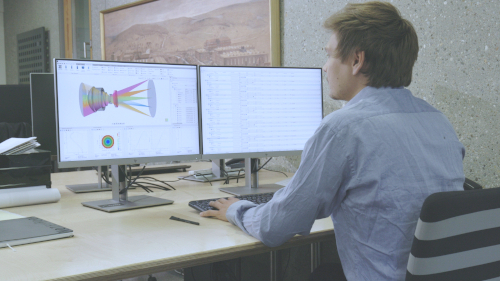
This 4-minute video defines global tolerances with the wizard and specific tolerances for one lens.
Video length: 3:47 min · Also on YouTube: How to Define Tolerances in QUADOA® Optical CAD
Frequently asked questions
Use the Default Tolerances wizard in the Tolerancing tab: select element, surface and assembly tolerances, enter values and distributions, and apply them as global tolerances.
Add an Element tolerance container under Specify ID, choose the lens identifier and add the tolerances for this lens. They replace the global tolerances of the same kind.
Add the tolerance to the element’s specific container with the value 0.0; otherwise the global value applies.
The tolerance is applied radially in the XY plane in a random direction, instead of independently in X and Y as with XY (Rect).
No. The sensitivity analysis perturbs each tolerance by its plus and minus value; the distribution is only used by the Monte Carlo analysis.