
Cooke Triplet Lens Design from Scratch in QUADOA® Optical CAD
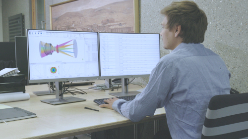
This tutorial designs a classical Cooke triplet camera lens from scratch in QUADOA® Optical CAD. Starting with an empty file, it sets up three singlet lenses, the object and image surfaces, the source with entrance pupil, fields and wavelengths, and the stop at the middle lens. The lens is then optimized for spot radius, its glasses are substituted from the SCHOTT catalog with the extended optimizer, and the result is evaluated with the MTF and a geometric image simulation.
Key points
- Specification: 450–650 nm, object at infinity, 10 mm entrance pupil diameter, back focal length about 50 mm, SCHOTT glasses.
- Start with three N-BK7 singlets and pre-tune them interactively toward a triplet shape.
- Place the stop at the middle lens, as usual for a Cooke triplet.
- Optimize the spot radius with the Merit Function Wizard, all curvatures variable and all apertures unlocked.
- For glass substitution, mark materials as Substitute and use the Extended or Global Optimization; the Local Optimizer cannot exchange materials.
Terms used in this article
- Cooke triplet
- A classic three-element camera lens: two positive outer lenses and a negative middle lens, with the stop near the middle.
- Back focal length
- The distance from the last lens surface to the image plane.
- Merit function
- The function that the optimizer minimizes, built from optimization goals such as spot radius.
- Glass substitution
- Optimization in which the optimizer may replace lens materials with glasses from an allowed list.
Lens specification
| Parameter | Value |
|---|---|
| Wavelength range | Visible, about 450 nm to 650 nm |
| Object distance | Infinity |
| Entrance pupil diameter | 10 mm |
| Field | Sampled from 0° to 15° in 5° steps |
| Back focal length | About 50 mm |
| Glass catalog | SCHOTT |
Step 1: Build the start system
- Start with a new, empty file.
- Add a singlet with the Singlet Lens button, using a basic material such as N-BK7 from SCHOTT, and duplicate it twice to get three lenses.
- Add an object space surface and drag it in front of the first lens.
- Add an image space surface after the last lens and position it 50 mm relative to the last lens surface, the target back focal length.
- Add air spaces between the lenses.
Step 2: Define source, fields, stop and wavelengths
Switch from the Optical Design Editor to the System Setup editor and open the sequence under Sequences.
- Set the Source Type to Plane WF (plane wavefront), so the rays come from infinity.
- Set the Aperture Type to Entrance Pupil with an aperture radius of 5 mm (10 mm diameter).
- In the source’s field settings, add three fields to sample 0° to 15° in 5° steps.
- Move the stop surface from the first lens to the second (middle) lens, as typical for a Cooke triplet: set the Stop Surface parameter of the sequence, or right-click the surface and choose Make Stop.
- In the wavelength settings, add the visible wavelengths and remove the original wavelength. A right-click on the wavelength container offers common wavelengths and predefined groups of wavelengths.
- Choose the central wavelength as the primary wavelength, which is the usual choice for polychromatic imaging systems.
Aperture type and speed: With the aperture type Entrance Pupil, the chief ray of each field passes through the center of the stop. It is much faster than From Stop, which aims the rays to fill the stop aperture exactly. For very large field angles or strong aberrations in front of the stop, the pupil sampling may become distorted.
Tip: Since the expected solution is known, pre-condition the system: tune the lenses interactively until the layout roughly resembles a Cooke triplet. This guides the optimizer toward the right solution.
Step 3: Optimize the curvatures
- In the Optimization tab, open the Merit Function Wizard, keep the defaults and choose Spot Radius as the main goal.
- Make the curvatures of all surfaces variable, individually or with the button for the whole system.
- Unlock all apertures so they are computed from the rays, with the Unlock all Apertures button in the menu bar of the Optical Design Editor. This avoids clipped rays during optimization (best practice; see floating apertures).
- Run the Local Optimizer. It finishes in about half a second.
Vignetted rays: If rays are vignetted when the optimizer starts, QUADOA® shows a warning; those rays are excluded from that run. In the next run they may be included again, so the spot can appear larger even though the merit function improved.
The first result already gives a good spot. The lenses are rather bulky, so reduce their thickness and run the optimization again for a cleaner design.
Step 4: Optimize the glass choice
So far all three lenses are N-BK7. To improve performance, let the optimizer exchange the materials:
- Mark all materials as Substitute.
- Define the allowed substitute materials, in this tutorial the whole SCHOTT catalog.
- Run the Extended Optimization. Material substitution works only with the Extended and Global optimizers; the Local Optimizer strictly searches the nearest minimum and does not make the “jumps” that a material change requires.
- In the optimizer dialog, the Glass Selector can be set to Smart (chooses glasses by their dispersion; usually better results) or Random (recommended if other glass properties, such as transmission or thermal expansion, affect the merit function).
- Optionally enable the automatic update of the 3D view and plots to watch the performance improve during the optimization.
Alternative with the Local Optimizer: convert the materials to model materials (right-click), set index and Abbe number as variables, and add a Model Material Offset Target to the merit function, which penalizes index/Abbe combinations that no real glass in the substitute catalog offers. Afterwards, replace the model materials with the best-fitting catalog glasses and re-optimize briefly. This method is usually faster than substitution.
Step 5: Evaluate the design
- MTF: on axis, the primary wavelength is close to diffraction limited. Other fields and wavelengths are not perfect in every case, but good for a short example design.
- Geometric image analysis: simulates the image as it would appear on the camera sensor.
The model files for each step are available via the link below the video on YouTube, so you can follow along.
Video tutorial: designing a Cooke triplet
This 9-minute video designs the Cooke triplet described in this article from an empty file to the final MTF and image simulation.
Video length: 8:52 min · Also on YouTube: Cooke Triplet Lens Design with QUADOA® Optical CAD
Frequently asked questions
In System Setup, set the Source Type of the sequence to Plane Wavefront.
Set the Aperture Type of the source to Entrance Pupil and enter the aperture radius, for example 5 mm for a 10 mm entrance pupil diameter.
Typically at the middle lens. In QUADOA®, move the stop surface to the second lens in the sequence settings.
Unlocked (floating) apertures are computed from the rays, so no rays are clipped while the optimizer changes the lens shapes.
The Local Optimizer only searches the nearest minimum and does not substitute materials. Mark the materials as Substitute, define the allowed substitute glasses and use the Extended or Global Optimization. Alternatively, optimize index and Abbe number of model materials with the Local Optimizer.
Use the Geometric Image Analysis, which simulates the image as it would appear on the camera sensor.