


Floating Apertures and Lens Settings in Quadoa Optical CAD
1. Introduction
This tutorial describes the configuration and behavior of Floating Apertures within the optical design workflow in the optical design software Quadoa Optical CAD.
It explains how to activate floating apertures, define aperture margins, and manage aperture behavior in multi-configuration models.
2. Floating Apertures
By default, each surface has a single circular aperture. The aperture radius can be defined as either fixed or floating. If set to fixed, the radius is explicitly determined by the value entered by the user. If set to floating, the radius is calculated automatically based on the ray-tracing results. In this case, the computed radius is the minimum required to ensure that all rays pass through the aperture.
Floating apertures can be enabled directly in the lens parameter interface within the Optical Design Editor.
Procedure
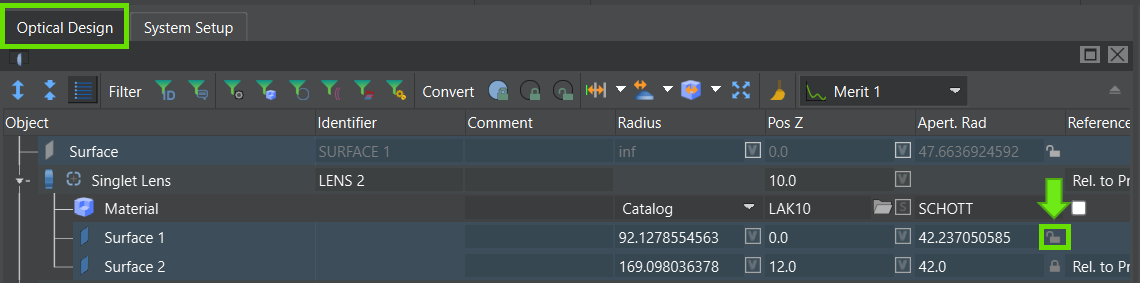
In the Optical Design Editor, navigate to the lens data where the Aperture Radius field is displayed. Click the lock icon next to the Aperture Radius field. Ensure the lock icon is shown as unlocked.
Activate Floating Apertures
When the lock icon is open, the Floating Aperture functionality is active.
3. Lens Edge and Aperture Settings
In addition to the aperture radius, further properties related to the aperture and lens edge behavior can be defined, such as aperture margins, linked apertures, and the addition of flanges or chamfers (See also the flanges and chamfers video tutorial).
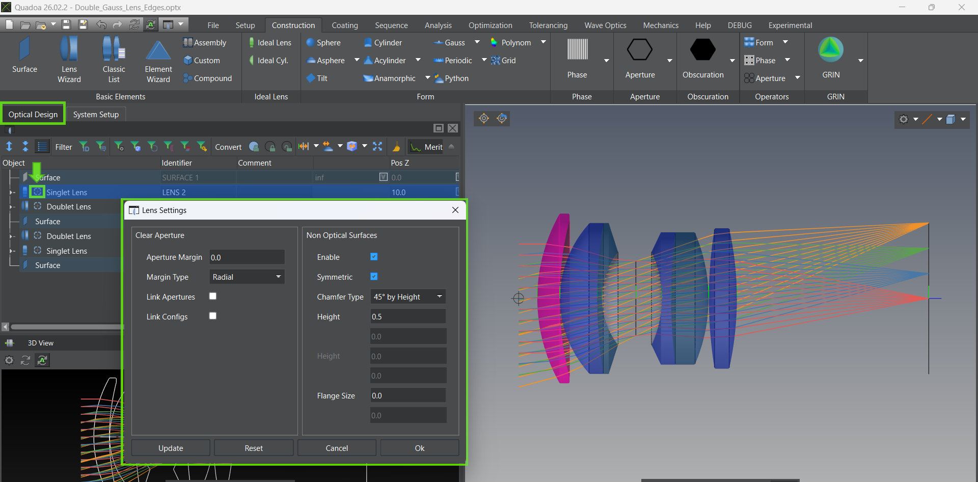
These settings can be configured in the Lens Settings Editor, which can be opened directly from the Optical Design Editor.
Procedure
Select the desired lens element in the Optical Design Editor. Click the plus (+) icon in the lens interface next to the lens type description.. The Lens Settings Editor will open.
Lens Settings Editor
4. Aperture Margin
The Aperture Margin defines the region outside the clear aperture which inscribes all traced rays. It effectively enlarges the aperture radius by the specified amount of the margin.
Example: If an Radial Aperture Margin of 2 mm is entered, the physical aperture radius is extended by 2 mm beyond the clear aperture.
Important: Aperture Margin settings are only applied when the Floating Aperture is enabled (lock icon open).
4.1 Aperture Margin Types
Two options are available for defining how the additional margin is applied beyond the floating aperture radius.
Radial
The margin is defined perpendicular to the optical axis. The specified value (e.g., 2 mm) is added straight outward perpendicular to the optical axis
Along Surface
The margin is defined along the surface tangent. The specified value (e.g., 2 mm) is added along the surface tangent. The overall aperture radius is increased by the entered margin multiplied by the cosine of the surface angle at the clear aperture.
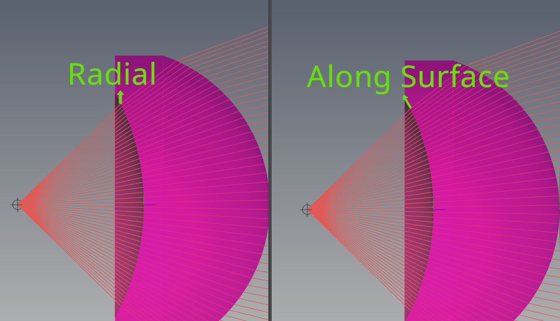
Radial and Along Surface Aperture Margin
4.2 Impact on Optimization
During optimization, it is often desirable to keep the aperture radius floating so that it can automatically adapt to changes in the ray footprint. In addition, edge thicknesses and air gaps between lenses must be properly controlled, taking into account that the physical aperture is typically larger than the clear aperture. For this reason, it is recommended to define the aperture margin before starting the optimization whenever constraints on edge thickness or air spaces are included in the merit function.
During optimization
Edge thickness is always calculated based on the full aperture, including any defined aperture margin. The margin can be used to accommodate mechanical mounting requirements or to provide additional space outside the clear aperture that may be required for polishing.
5. Link Aperture (Surface Synchronization)
For manufacturing reasons, it is often required that both surfaces of a singlet lens have identical aperture sizes. This can be achieved by activating the Link Apertures parameter, which is available in the Lens Edge Settings.
Procedure
Open the Lens Settings Editor. Enable the Link Aperture checkbox. Apply this setting to all relevant lens elements.
When activated, these steps are performed
The floating aperture radius is computed for both surfaces as described in (2). The larger aperture radius is determined. The smaller aperture is automatically resized to match the larger one.
6. Multi-Configuration Models (Link Configs)
6.1 Configuration-Dependent Floating Apertures
In multi-configuration models (for example, zoom systems), the floating aperture radius may vary from one configuration to another. In the physical system, however, the lens is typically the same for all configurations, meaning that only a single physical aperture radius exists. This behavior can be implemented by activating the Link Configs parameter in the Lens Edge Settings.
Procedure
Open the Lens Settings Editor. Enable the Link Config option. Apply this setting to all relevant lens elements.
When activated, the following steps are perfomred
The floating aperture radius is computed for all configurations as described in (2). The largest aperture radius is identified. This maximum aperture radius is applied to all configurations.
7. Combined Usage
All described settings can be combined.
Floating Apertures activation. Aperture Margin definition (Radial or Along Surface). Link Aperture (surface synchronization). Link Config (configuration synchronization).
These options allow full control over aperture geometry, edge behavior, manufacturability, and multi-configuration consistency.
Watch Floating Aperture Video Tutorial
Video (5:04 min)
Floating Apertures and Lens Edge Settings in QUADOA® Optical CAD.
|
|
|---|
| Activate Floating Apertures |
|
|
|---|
| Lens Settings Editor |
|
|
|---|
| Radial and Along Surface Aperture Margin |
|
|
|---|
|
|