
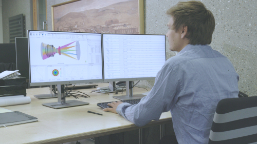


3D-View Editor and Mouse Selection Modes in QUADOA® Optical CAD
The 3D-View Editor in QUADOA® Optical CAD lets you select lenses, surfaces and single rays directly in the 3D view and work on them there, without switching to the Optical Design Editor. This tutorial shows the three mouse selection modes, how to move, rotate or modify a lens or surface from its 3D menu, how to use sliders for a quick visual optimization, and how to open the ray trace report for a single ray, including polarization data.
Key points
- The Mouse Selection Mode icon at the bottom of the 3D view switches between lens, surface and ray selection; the manual also lists selection of a whole assembly or only an aperture.
- Double-click a highlighted lens or surface to jump to it in the Optical Design Editor.
- Right-click a lens or surface to open its 3D menu and edit parameters such as position, rotation, radius or aperture.
- Click a parameter in the 3D menu to open a slider for interactive changes, for example to rotate a lens during a manual visual optimization.
- In ray selection mode, double-click a ray to open the ray trace report with ray direction, intersections and optional parameters.
- With a polarized light source, the ray trace report also shows polarization data such as electric field, ellipticity and Stokes parameters.
Terms used in this article
- 3D view
- The interactive three-dimensional view of the optical system in QUADOA®.
- Optical Design Editor
- The editor that lists all elements, surfaces and parameters of the optical system.
- Active cell pointer
- The marker that shows which cell of the Optical Design Editor is currently selected.
- Mouse selection mode
- Defines what the mouse selects in the 3D view: whole lenses, single surfaces or single rays.
- Lens 3D menu / Surface 3D menu
- Context menus opened with a right-click in the 3D view, listing the parameters of the selected lens or surface.
- Ray trace report
- A report with the data of a single traced ray, such as direction and intersection points at each surface.
What are the mouse selection modes?
The mouse selection mode decides what is highlighted and selected when you move the mouse over the 3D view. You switch it with the Mouse Selection Mode icon at the very bottom of the 3D view.
| Mode | Highlighted on hover | Double-click (left) | Right-click |
|---|---|---|---|
| Lens selection | The whole lens | Jumps to the lens in the Optical Design Editor | Opens the Lens 3D menu |
| Surface selection | A single surface | Jumps to the surface in the Optical Design Editor | Opens the Surface 3D menu |
| Ray selection | A single ray | Opens the ray trace report for that ray | – |
The manual also describes Select Assembly (selects the whole assembly an element belongs to) and Select Aperture (selects only the aperture).
Steps
- Click the Mouse Selection Mode icon at the bottom of the 3D view.
- Choose lens, surface or ray selection.
- Move the mouse over the system: the lens, surface or ray under the pointer is highlighted.
How to edit a lens in the 3D view
In lens selection mode, the whole lens is highlighted when you hover over it, and you can change its parameters from the Lens 3D menu.
Steps
- Select the lens selection mode.
- Hover over a lens in the 3D view. The whole lens is highlighted.
- To find the lens in the Optical Design Editor, double-click it with the left mouse button. The active cell pointer jumps to the selected lens.
- To edit the lens, right-click it. The Lens 3D menu opens.
- Change a parameter. For example, set the position in Z to 20: the lens moves to the new position.
What you can do in the Lens 3D menu
| Action | Description |
|---|---|
| Move | Change the lens position, for example in Z |
| Rotate | Rotate the lens, also interactively with a slider |
| Focus | Change the power of the lens by changing the radii of its first and last surface |
| Bend | Change the bending of the lens by changing the radii of all its surfaces |
| Flip | Flip the whole lens |
| Relative / absolute | Switch the position between relative and absolute coordinates |
| Convert to doublet | Convert a singlet lens into a doublet lens (in general an N-let into an (N+1)-let). The new surface gets the same material, so the optics do not change until you change the material or form. |
| Merge | Merge the lens with the previous lens into a cemented lens; the first surface of the lens is removed |
| Delete / Duplicate | Delete the lens or create a copy of it |
| Surfaces | Select a single surface of the lens at the bottom of the menu and edit its parameters |
Focus and Bend are only available if every surface of the lens has an active curvature parameter, for example the default radius or a spherical or aspherical form.
How to use sliders for a visual optimization
Instead of typing a value, you can change many parameters continuously with a slider and watch the effect in the 3D view at the same time.
- Open the Lens 3D menu with a right-click on the lens.
- Click a parameter, for example the rotation. A slider opens.
- Drag the slider handle. The lens rotates in the 3D view as you move it.
This is useful for a manual, visual lens optimization: you see immediately how the change affects the ray path. To learn more about sliders, see the slider interface tutorial in the Learning Center.
How to edit a single surface in the 3D view
In surface selection mode, only the single surface under the mouse pointer is highlighted, not the whole lens.
Steps
- Select the surface selection mode.
- Hover over a lens. Only the surface under the pointer is highlighted.
- Double-click the surface to jump to it in the Optical Design Editor.
- Right-click the surface to open the Surface 3D menu.
What you can do in the Surface 3D menu
- Change the radius of the surface
- Change the aperture, and lock or unlock it (see floating apertures)
- Move or rotate the surface
- Flip the surface
- Switch the position between relative and absolute
How to inspect a single ray (ray trace report)
In ray selection mode you can pick any single ray in the 3D view and see all its data in the ray trace report.
Steps
- Select the ray selection mode.
- Hover over the system. Single rays are highlighted.
- Double-click a ray. The ray trace report opens.
- To show more data, click the parameter icon in the report and select additional parameters.
| Shown by default | Examples of additional parameters |
|---|---|
| Ray direction Ray intersection with each surface | Angle to the surface Surface normal at the intersection Optical path length Intensity (flux) of the ray |
How to show polarization data for a ray
For systems with polarized light, the ray trace report can also show the polarization state of the selected ray. Polarization ray tracing must be enabled for the sequence: its source polarization type must not be None.
- Set the light source to polarized light, for example circular polarization.
- Double-click a ray in ray selection mode to open the ray trace report.
- Select the polarization parameters you want to see.
Available polarization data includes the electric field, the orientation, the ellipticity, the Stokes parameters and the degree of polarization. For more on polarization ray tracing, see the polarization tutorials.
Video tutorial: 3D-View Editor and selection modes
This 6-minute video shows the three mouse selection modes, the lens and surface 3D menus, and the ray trace report including polarization data.
Video length: 5:46 min · Also on YouTube: 3D-View Editor in QUADOA® Optical CAD
Frequently asked questions
Choose the lens selection mode with the Mouse Selection Mode icon at the bottom of the 3D view, then right-click a lens. The Lens 3D menu opens, where you can move, rotate, bend, flip, duplicate or delete the lens and change other parameters.
Lens selection highlights and selects whole lenses, surface selection highlights single surfaces, and ray selection highlights single rays. You switch between them with the Mouse Selection Mode icon at the bottom of the 3D view.
Double-click the highlighted lens or surface with the left mouse button. The active cell pointer in the Optical Design Editor jumps directly to the selected lens or surface.
Yes. In the Lens 3D menu, click a parameter such as the rotation to open a slider. Dragging the slider updates the 3D view immediately, which is useful for a manual visual optimization.
Choose the ray selection mode and double-click a ray in the 3D view. The ray trace report opens with the ray direction and intersection points. More parameters, such as angle, surface normal and optical length, can be added with the parameter icon.
Yes. With a polarized light source, for example circular polarization, the ray trace report can show the electric field, orientation, ellipticity, Stokes parameters and degree of polarization of the selected ray.
No. Additional 3D-View Windows, opened from the Analysis tab, are for visualization only, for example to show other configurations. Lenses are edited in the main 3D view.