


First-Order Thermal Analysis of a Beam Expander in Quadoa
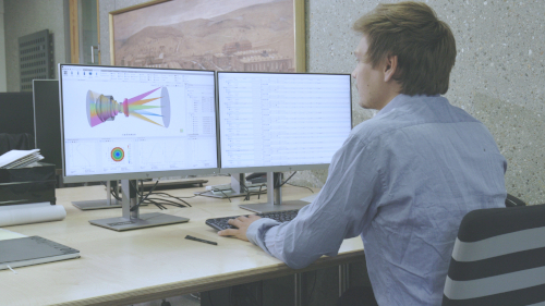
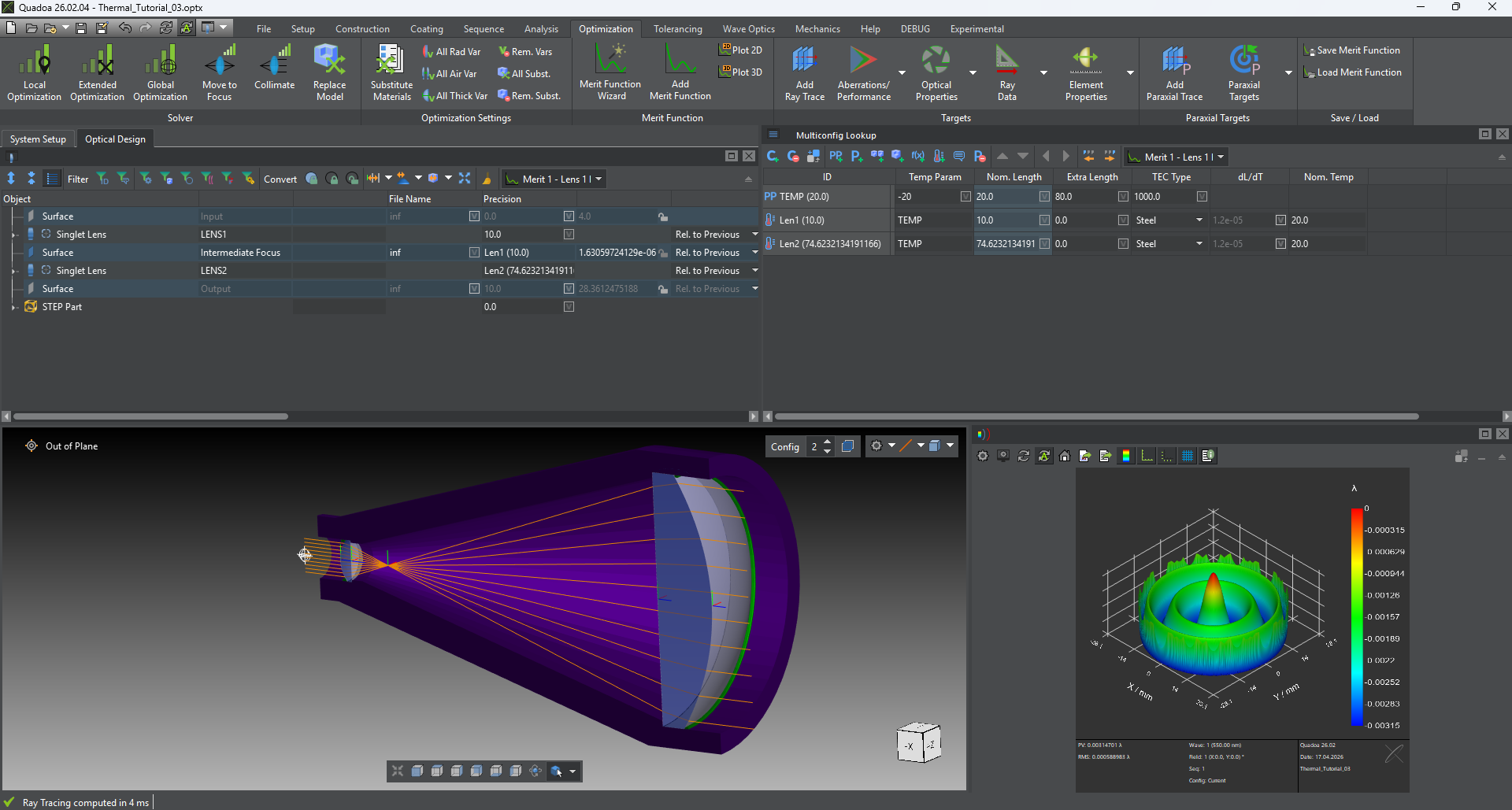
System Overview
|
|---|
| First-Order Thermal Analysis of a Beam Expander in Quadoa |
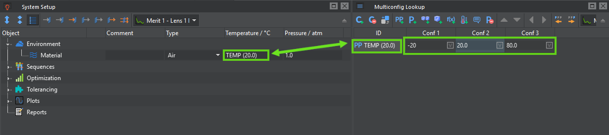
Multi-Configuration Setup
|
|---|
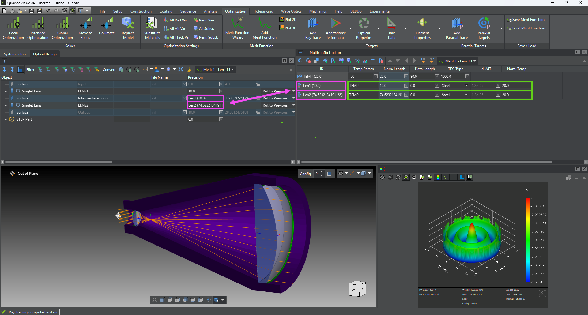
| Defining a Temperature Parameter in the Multiconfig-Lookup |
|
|---|
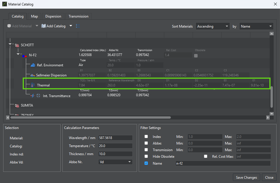
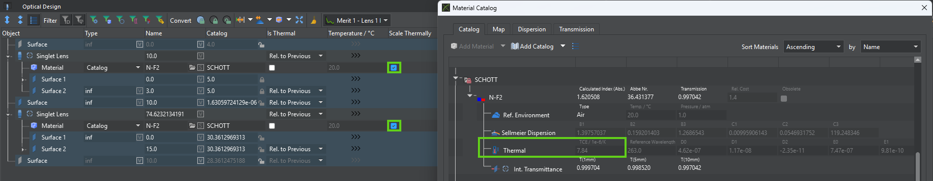
| Thermal Dispersion Coefficients in the Materials Catalog |
Thermal Expansion of Optical Elements
|
|---|
| Thermal Coefficient of Expansion (TCE) in the Materials Catalog |
Mechanical Mounting and Thermal Lengths
|
|---|
| Adding Thermal Lengths Parameters |
System Optimization Across Temperature
Variable Definition and Optimization
|
|---|
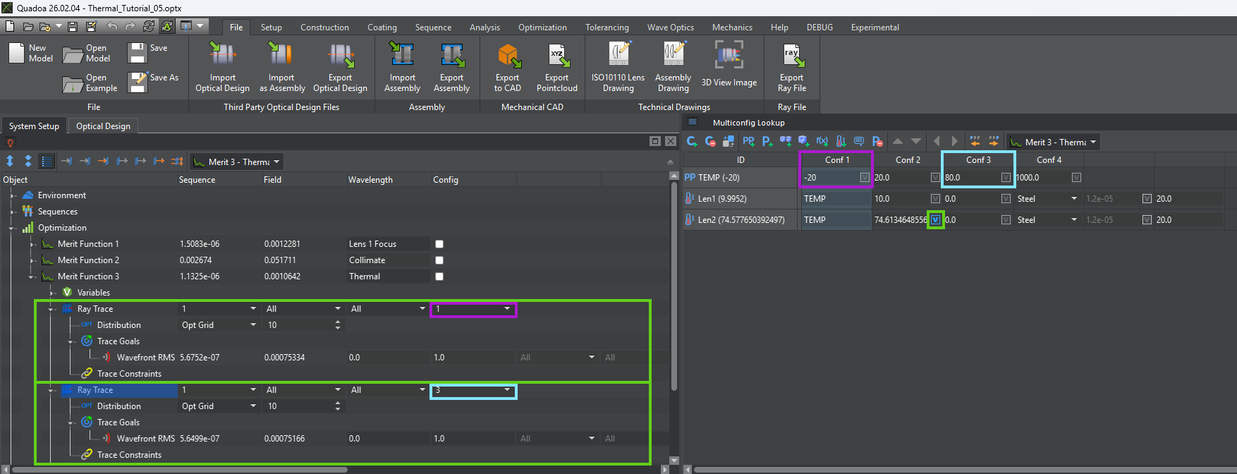
| System Optimization Across Temperature |
Conclusion
-
Thermal expansion of the aspheric lenses. -
Temperature-dependent changes in refractive index. -
Mechanical expansion of the mounting structure
|
|