


Defining Complex Lens Edge Geometries: Chamfers and Flanges
1. Introduction
This tutorial explains how to define complex lens edge geometries, such as chamfers and flanges, in Quadoa Optical CAD.
This feature makes it possible to streamline the design and integration workflow by defining the complete lens geometry, including non-optical surfaces, directly within the optical design software. With the geometries already defined, a post-processing step that is typically performed in mechanical design software can be skipped. Furthermore, lens drawings according to ISO 10110, including the chamfer specification, can be generated directly.
2. Chamfers
Chamfers are often added to the outer perimeter of a lens to reduce the risk of chipping during handling or mounting. Furthermore, larger chamfers can be used to reduce the weight of the lens or to make space for other components, such as iris diaphragms. Chamfers are always added outside the clear aperture of the lens. Therefore, the physical diameter of the lens increases when a chamfer is added.
Procedure to enable chamfers
Select the desired lens element in the Optical Design Editor where you want to add a chamfer. Click the plus (+) icon in the lens interface next to the lens type description.. The Lens Settings Editor will open. Activate the Enable checkbox in the Lens Settings Editor under Non-Optical Surfaces to enable Chamfers.
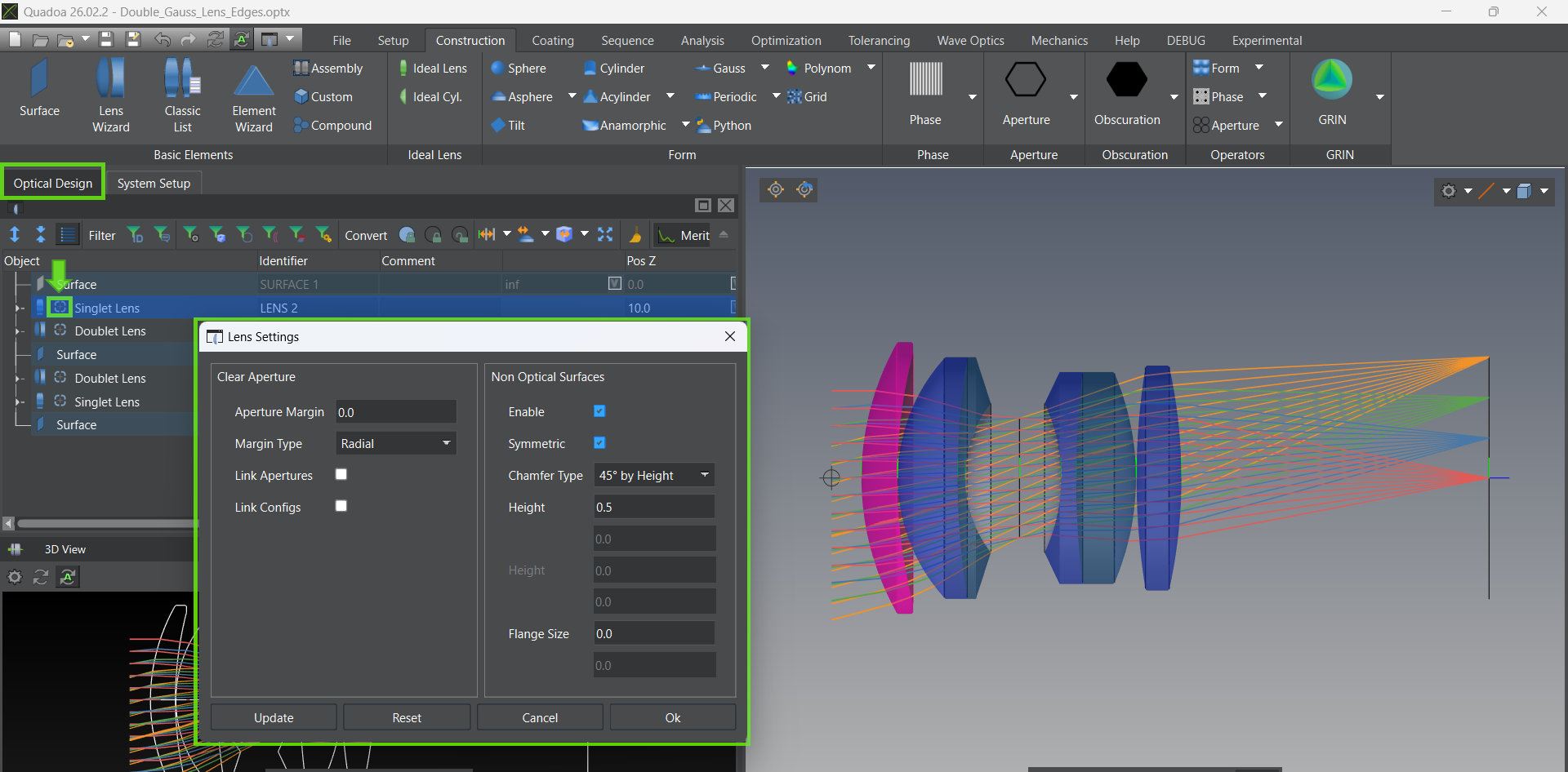
Lens Settings Editor
2.1 Symmetric Chamfer
In many cases, the same chamfer geometry is applied to all lens edges. In this situation, a symmetrical chamfer can be used. This way, the geometry only needs to be specified once, and it will be applied to all edges of the lens.
Procedure to add symmetric chamfer
Select the lens in the Optical Design Editor where you want to add the chamfer. Click the plus (+) icon. Check Symmetric to make chamfers identical on both surfaces. Specify the value.
2.2 Asymmetric Chamfer
In addition to symmetric configurations, it is also possible to define asymmetric chamfers. This allows different chamfer geometries on each surface of a lens, providing greater flexibility to meet specific mechanical, manufacturing, or assembly requirements.
Procedure to add asymmetric chamfer
Select the lens in the Optical Design Editor where you want to add the chamfer. Click the plus (+) icon. Leave Symmetric unchecked for asymmetric chamfers and specify different values for each surface. Specify the value for both surfaces.
Note: Chamfers can also be applied to cemented lens elements. In this case, the chamfer is added only to the outer surfaces of the lens, leaving the cemented surface unchanged.
2.3 Define Chamfer Geometry
The chamfer geometry can be defined in several ways. Various parameterization options allow flexible, direct control of the chamfer size and angles without the need to convert parameters if they are specified in a different format.
Chamfer Geometry Options
45° by Height: This option creates a 45° chamfer. The height of the chamfer (measured perpendicular to the optical axis) is specified by the user. 45° by Diagonal: This option creates a 45° chamfer in which the length of the chamfer surface itself matches the value entered by the user. Height & Length: This option creates a chamfer defined by its height (measured perpendicular to the optical axis) and its length (measured parallel to the optical axis). Angle & Height: This option creates a chamfer defined by its height and the angle between the chamfer surface and the outer surface of the lens (parallel to the optical axis).
3. Flanges
Especially for injection-molded polymer lenses, the geometry of the non-optical surfaces is subject to far fewer manufacturing constraints. This freedom can be used to directly include features that are required for the mounting of the elements. One of the most common geometries used for this type of feature is a flange.
Flanges can be added to a lens and configured within the Lens Settings Editor.
Procedure to add flanges
Open the Lens Settings Editor for the lens. Define the flange size at the bottom of the editor.
If the clear aperture differs between the two surfaces, the size of the flange is based on the smaller clear aperture. The size of the second flange is automatically increased to close the gap between the specified flange and the clear aperture.
Note: It is important to note that chamfers and flanges always begin at the clear aperture. This means that while the overall lens diameter increases to accommodate the chamfer, the clear aperture which inscribes all traced rays remains unchanged.
Watch Chamfer and Flanges Video Tutorial
Video (5:27 min)
Chamfers and Flanges in QUADOA® Optical CAD.
|
|
|---|
| Lens Settings Editor |
2.1 Symmetric Chamfer
Select the lens in the Optical Design Editor where you want to add the chamfer. Click the plus (+) icon. Check Symmetric to make chamfers identical on both surfaces. Specify the value.
2.2 Asymmetric Chamfer
Select the lens in the Optical Design Editor where you want to add the chamfer. Click the plus (+) icon. Leave Symmetric unchecked for asymmetric chamfers and specify different values for each surface. Specify the value for both surfaces.
2.3 Define Chamfer Geometry
45° by Height: This option creates a 45° chamfer. The height of the chamfer (measured perpendicular to the optical axis) is specified by the user. 45° by Diagonal: This option creates a 45° chamfer in which the length of the chamfer surface itself matches the value entered by the user. Height & Length: This option creates a chamfer defined by its height (measured perpendicular to the optical axis) and its length (measured parallel to the optical axis). Angle & Height: This option creates a chamfer defined by its height and the angle between the chamfer surface and the outer surface of the lens (parallel to the optical axis).
|
|
3. Flanges
Open the Lens Settings Editor for the lens. Define the flange size at the bottom of the editor.
Watch Chamfer and Flanges Video Tutorial
|
|
|---|
|
|