
Ray Tracing and Sequence Settings in QUADOA® Optical CAD
All ray tracing settings of a sequence in QUADOA® Optical CAD are defined in the System Setup Editor: the sequence itself holds the aperture type, field type, stop surface and image space, and its source holds the source type, wavelengths, fields, ray distribution, apodization and polarization. This article lists the options with the recommendations from the manual.
Key points
- Sequence settings: aperture type, field type, stop surface, OPD reference and image space (focal or afocal).
- Source settings: source type, wavelengths, fields, distribution, apodization and polarization.
- Source types: Point Source, Plane WF, WF from Surface, Extended, From Ray File, Gaussian Beam.
- The ray distribution of the sequence only affects the 3D view; plots and optimization have their own sampling.
- Add wavelengths and fields with a right-click or the Insert key.
Terms used in this article
- Stop surface
- The surface whose center all chief rays pass through.
- Aperture type
- Defines how the size of the ray bundle is specified, e.g. by object-space NA or entrance pupil.
- Apodization
- The intensity distribution over the pupil, applied by weighting the ray flux.
- Afocal image space
- Image space with collimated rays, as in telescopes or beam expanders.
Which settings belong to the sequence?
Open the System Setup Editor (Windows icon) and expand Sequences. The sequence, for example the Auto Sequence, has these main settings:
| Setting | Options |
|---|---|
| Aperture Type | Object Space NA and Entrance Pupil (fast; chief rays through the stop center), From Stop (rays fill the fixed stop aperture exactly, slower), None (rays independent of a stop, for illumination) |
| Field Type | Obj. Height (point sources only), Angle, Img. Height (focal systems), Free (aperture type None) |
| Stop Surface | Surface whose center the chief rays pass; also set with right-click → Make Stop |
| OPD Reference | Exit Pupil (imaging), Afocal Exit Pupil (collimated output), Abs over Img (wavefront at the last surface, e.g. interferometers), Abs over EP |
| Image Space | Focal or Afocal |
The manual recommends Object Space NA or Entrance Pupil whenever possible because they are much faster than From Stop; with very large field angles or strong aberrations before the stop, the pupil sampling may become distorted.
Which source types are available?
| Source Type | Use |
|---|---|
| Point Source | Object at a finite distance, perfect point source |
| Plane WF | Object at infinity (plane wavefront) |
| WF from Surface | Wavefront with the shape of the first surface, e.g. measured wavefronts or null optics design (see CGH design) |
| Extended | Extended sources with their own distributions, e.g. disks, Gaussian beams or patterns |
| From Ray File | Measured source data from manufacturers of LEDs, lamps or lasers; the ray file must be in the model folder |
| Gaussian Beam | Gaussian beam propagation; most analysis plots are then not available |
How to set wavelengths and fields
- Wavelengths: right-click the wavelength container to add common wavelengths, predefined groups of wavelengths, or a custom wavelength in nm. Choose a primary wavelength, typically the central one; it is the reference for aberration plots. Each wavelength has a weight for optimization.
- Fields: at the bottom of the source, in the Fields container. Add fields with a right-click → Add Field or the Insert key. The available field parameters (tilt or decenter) depend on the field type of the sequence; each field also has a weight and vignetting factors.
What does the ray distribution control?
Important: The distribution of the sequence only defines the rays shown in the 3D view. Analysis plots and the optimization use their own sampling, set in the plot and optimization settings.
Available distributions include single ray, X, Y and XY fans, ring, equal or concentric rings, hexagonal grid, optimized grid, rectangular grid, random and quasi-random rays. Extended and Gaussian beam sources have their own distributions, for example disks or single-mode and multi-mode fiber outputs. Keep the number of 3D-view rays low for a fast user interface; see performance tips.
Apodization and polarization
- Apodization defines how the intensity is distributed over the pupil, for example constant, Gaussian or super-Gaussian, by weighting the ray flux. It affects all calculations that use the flux, such as irradiance, PSF and MTF.
- Polarization sets the polarization state of the rays: Jones-calculus types (linear, circular, Jones complex, Jones phase, random) or a Stokes vector for partially polarized light with Müller matrices. See polarized light source.
Video tutorial: ray tracing and sequence settings
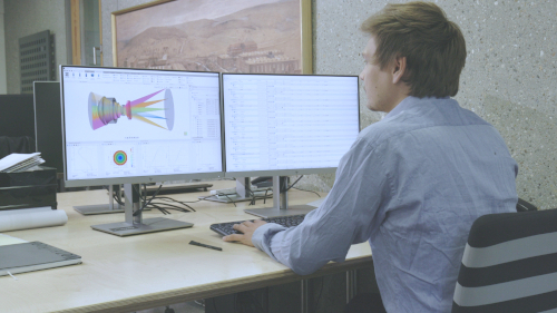
This 3-minute video walks through the sequence and source settings in the System Setup Editor.
Video length: 3:03 min · Also on YouTube: Ray Tracing and Sequence Settings in QUADOA® Optical CAD
Frequently asked questions
In the System Setup Editor under Sequences. The sequence holds aperture type, field type, stop surface and image space; its source holds source type, wavelengths, fields, distribution, apodization and polarization.
No. The distribution of the sequence only affects the rays in the 3D view. Analysis plots and the optimization use their own sampling.
Object Space NA or Entrance Pupil whenever possible, because they are much faster than From Stop. From Stop fills a fixed stop aperture exactly; None is meant for illumination systems.
Select the Fields container and press the Insert key, or right-click and choose Add Field.
Plane WF (plane wavefront).