
Polarized Light Source in QUADOA® Optical CAD
The polarization of the light in QUADOA® Optical CAD is set in the Polarization item of the source of each sequence. Linear, circular and any elliptical state can be defined with the Jones calculus; partially polarized and unpolarized light with a Stokes vector. Once polarization is set, the 3D view draws the polarization state along the rays, and the polarization map shows it across the pupil. The example model “linear on curved surface” is in the examples folder.
Key points
- Set the polarization in System Setup → Sequence → Source → Polarization.
- Types: None, Linear, Circular, Jones Complex, Jones Phase, Stokes, Random.
- Linear: angle of the polarization plane; 0° is horizontal.
- Jones Complex and Jones Phase define any elliptical polarization.
- For unpolarized light with polarization ray tracing, use Stokes (1, 0, 0, 0) or Random; None switches polarization ray tracing off.
- The polarization map in the Analysis tab shows the polarization ellipses over the pupil.
Terms used in this article
- Jones vector
- A two-component complex vector that describes fully polarized light, including its phase.
- Stokes vector
- Four parameters (I, Q, U, V) that also describe partially polarized light, without phase information.
- Polarization map
- A plot of the polarization ellipses over the pupil at a chosen surface.
How to set the polarization of the source
- Open the System Setup Editor and expand the sequence and its Source.
- Open the Polarization item and choose a type from the drop-down menu, for example Linear.
- Set its parameters, for example an angle of 45°.
The 3D view now draws the polarization state on the rays and updates immediately when you change the settings. The Reference parameter defines the coordinate system in which the polarization is specified; see polarization capabilities.
Which polarization types are available?
| Type | Parameters | Use |
|---|---|---|
| None | – | Polarization ray tracing off; coatings are calculated for unpolarized light |
| Linear | Angle (0° = horizontal) | Linearly polarized light, e.g. lasers |
| Circular | Left or right | Circularly polarized light |
| Jones Complex | Real and imaginary parts of x and y (Ex, Ecx, Ey, Ecy) | Any elliptical polarization |
| Jones Phase | Amplitude and phase (in waves) of x and y | Any elliptical polarization |
| Stokes | I, Q, U, V (S0–S3) | Partially polarized or unpolarized light; Jones elements are converted to Müller matrices |
| Random | – | Random elliptical state per ray; behaves like unpolarized light with enough rays |
Jones vectors are always normalized to 1, Stokes vectors to I = 1. With a Stokes source, the phase of the field is not retained.
How to visualize the polarization with the polarization map
- Open the Analysis tab and choose the Polarization Map on the right.
- Open the plot settings and select sequence, field, wavelength and the surface to analyze.
- Increase the Sampling for more ellipses across the pupil.
- Set Status to analyze the ray before or after the interaction with the surface.
- Check Show Arrow to indicate the handedness of the polarization; Scale changes the size of the ellipses.
Other polarization analyses are the transmission fan plot, the Poincaré sphere and the ray trace report.
Video tutorial: polarized light sources
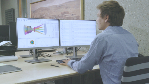
This 3-minute video sets different source polarizations and shows them in the 3D view and the polarization map.
Video length: 2:47 min · Also on YouTube: How to Define a Polarized Light Source in QUADOA® Optical CAD
Frequently asked questions
In the System Setup Editor, in the Polarization item of the source of each sequence.
Use Jones Complex (real and imaginary parts of the x and y components) or Jones Phase (amplitude and phase in waves of each component).
Use a Stokes source with I = 1 and Q = U = V = 0, or the Random type. The type None switches polarization ray tracing off completely.
Yes. Check Show Arrow in the polarization map settings to indicate the handedness.