Importing Mechanics and Ray Intersection Analysis in QUADOA® Optical CAD
QUADOA® Optical CAD can include mechanical parts, such as lens mounts or housings, directly in the optical model and check whether any rays hit them. CAD parts are imported as STL, STEP or IGES files and positioned like any optical element. The Check Ray Intersection function counts the rays that hit the mechanics and colors each part green or red, so vignetting by mounts is found before anything is built.
Key points
- Add CAD parts in the Mechanics tab: STL, STEP (also colored) or IGES.
- The CAD file must be in the same folder as the optical model (*.optx).
- Parts are positioned with their own coordinate system, like any element.
- Check Ray Intersection counts intersecting rays and colors parts green (free) or red (hit).
- Simple primitives (cube, sphere, cylinder, tube) sketch mounts without CAD software.
- Importing mechanics requires the Mechanics Analyzer Toolbox; CAD export is part of the basic license.
Terms used in this article
- Mech part
- A mechanical component in the Optical Design Editor, imported from CAD or built from primitives.
- Ray intersection check
- An analysis that finds rays passing through mechanical parts.
- Meshing precision
- The maximum deviation of the triangulated CAD shape from the real shape, used for display and intersection.
How to import a mechanical part
- Copy the CAD file into the folder of the optical model (*.optx). If you save the model elsewhere, copy the file as well.
- In the Mechanics tab, click STL (or STEP / IGES). A new part appears in the Optical Design Editor.
- Enter the file name, for example
mounting.stl. The part appears in the 3D view. - Move it to the right place with its position parameters, like any other element.
For STEP and IGES files, the Precision parameter sets the maximum deviation of the meshed shape from the real shape, in length units. Small values give accurate intersections but can take long to compute for large or complex parts.
How to check for ray intersections
- In the Mechanics tab, click Check Ray Intersection (Analysis group).
- A message shows how many rays intersect the mechanics; in the video, 60 rays hit the mount of a microscope objective.
- Parts without intersections are highlighted green, parts with intersections red.
- Fix the problem, for example by reducing the aperture radius to 4.5 mm, and check again: now no rays intersect.
- Click Clear Highlight to restore the default colors.
Which formats and primitives are supported?
| Type | Details |
|---|---|
| STL | Meshed CAD file; parameter File Name |
| STEP | Including colored STEP models, whose colors replace the default mechanics color; parameters File Name and Precision |
| IGES | Parameters File Name and Precision |
| Primitives | Cube (Size X, Y, Z), sphere (Radius), cylinder (Length, Radius), tube (Length, Inner and Outer Radius), defined directly in QUADOA® |
In the other direction, Export to CAD writes the optical system, assemblies or single lenses as STEP, IGES or STL for mechanical designers. Mechanics can also define the building space of a design, as in the head-up display example.
Video tutorial: importing mechanics and intersection analysis
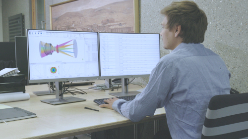
This 3-minute video imports an STL mount and checks a microscope objective for ray–mechanics intersections.
Video length: 2:54 min · Also on YouTube: Import Mechanical CAD Parts and Check Ray Intersections in QUADOA® Optical CAD
Frequently asked questions
STL, STEP (including colored STEP files) and IGES. Simple primitives such as cubes, spheres, cylinders and tubes can be created directly.
In the same folder as the optical model file (*.optx). If the model is saved to another location, the CAD file must be copied too.
Click Check Ray Intersection in the Mechanics tab. The number of intersecting rays is shown, and parts are highlighted green (no intersection) or red (intersection).
Importing mechanical components requires the Mechanics Analyzer Toolbox, which is not part of the basic license. Exporting CAD files is included in the basic version.