
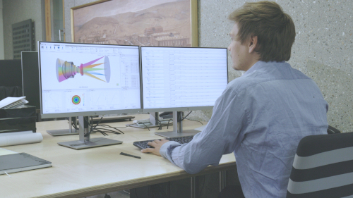


Head-Up Display (HUD) Design in QUADOA® Optical CAD
This tutorial designs an automotive head-up display (HUD) in QUADOA® Optical CAD, from the real windshield shape to the final image quality check. The windshield is imported as a point cloud and fitted with polynomials, the optics are fitted into a building space imported from CAD, a freeform mirror is optimized for spot size, and separate sequences check the image seen by the driver’s eye and whether sunlight can be reflected into the eye box. Multi-sequential ray tracing keeps all these light paths in one model.
Key points
- The windshield shape is imported from a CAD point cloud and fitted with polynomials.
- A dummy surface aligned to the chief ray serves as reference for placing the HUD optics.
- The building space under the dashboard is imported as a CAD part in the Mechanics tab.
- Optics: one freeform mirror (polynomial up to 4th order), one fold mirror and the display.
- Design sequence: virtual image → eye box (stop) → windshield → mirrors → display; reverse sequence with a 3 mm eye pupil for image quality.
- A third sequence checks that sunlight cannot be reflected from the display into the eye box.
Terms used in this article
- Head-up display
- A display that projects information as a virtual image in front of the windshield.
- Eye box
- The region in which the driver’s eyes can be placed while seeing the complete virtual image.
- Virtual image
- The image that appears to float in front of the windshield, here 2.5 m away.
- Building space
- The volume in the dashboard available for the HUD optics.
Step 1: Model the windshield
- Add a singlet for the windshield and assign material and thickness.
- Add a rectangular aperture with the windshield size and duplicate it to the second surface.
- Rotate the windshield around the X axis to its installation angle.
- Import the real shape: right-click the surface → Add Form → Import Point Cloud, select the point cloud exported from the mechanical CAD, choose a polynomial form and order for the fit, set all coefficients variable and Convert. The fit error is practically zero.
- Repeat for the second surface and set the identifier to
windshield.
The import works as described in adding measurement and FEM data.
Step 2: Eye box and virtual image
- Add two surfaces, eye box and virtual image, both in absolute coordinates.
- Place the virtual image 2.5 m in front of the windshield, 350 mm lower toward the street, and tilt it toward the street.
- Place the eye box at the driver’s head position, displaced to the side of the windshield center and slightly lower, with a rectangular aperture of 120 mm × 60 mm.
- Create a User Sequence from the virtual image to the eye box, with the eye box as stop surface and a rectangular ray grid.
- Add fields at the corners and sides of the virtual image (Insert key) by entering their decenter values.
Step 3: Align a reference surface to the chief ray
Everything is off-axis and the freeform windshield reflects at an angle, so a dummy surface aligned to the chief ray serves as reference for the HUD optics.
- Add a dummy surface in absolute coordinates, roughly below the windshield and pre-rotated.
- Extend the sequence: from the eye box to the windshield (Surface Action Reflection) and on to the dummy surface.
- Create a merit function with chief ray goals: chief ray position x = 0 and y = 0 on the dummy surface, chief ray incident angle = 0, and the chief ray of an outer field at x = 0 to fix the rotation.
- Make Z, X and all rotations of the dummy surface variable and run the Local Optimizer.
The surface is now perfectly aligned with the chief ray in position and rotation.
Step 4: Building space and HUD optics
- Import the building space (a bounding box exported from mechanical CAD) as a CAD part in the Mechanics tab; the file must be in the model folder. See importing mechanics.
- Add three surfaces: freeform mirror, fold mirror and display, and position them inside the building space.
- Extend the sequence by the freeform mirror and fold mirror (both Reflection) and the display as image surface.
Step 5: Optimize the freeform mirror
- Add a polynomial form up to the 4th order to the freeform mirror.
- Add a second merit function that minimizes the spot radius.
- Select this merit function above the Optical Design Editor and set all polynomial coefficients variable, except piston and tilt, which are covered by the position and rotation of the surface.
- Open a spot diagram and run the optimization.
Refinements: rotate the mirror slightly to keep distance from the wall of the building space and re-optimize; add a chief ray goal that centers the display on the central chief ray (with its position variable); and tilt the display so the chief ray does not hit it perpendicularly. Otherwise sunlight entering through the windshield could be reflected by the display into the driver’s eyes. Finally, add rectangular apertures to all elements and hide the dummy surface.
Step 6: Evaluate the real imaging path
The design sequence runs from the virtual image to the display, with the whole eye box as aperture. In reality, light goes from the display to the eye, and the aperture is the pupil of one eye.
- Duplicate the design sequence and revert its direction; hide the original.
- Adjust the fields to the size of the display.
- Add a surface eye directly after the eye box, positioned relative, with a 3 mm aperture, and make it the stop surface.
- Rotate the last surface by 180° around X or Y so the rays are drawn as real rather than virtual (dashed) rays. Rays always start in +Z of the object surface.
Now select this sequence in the plots to evaluate the spots on the virtual image, the footprint diagram on the freeform mirror, the distortion and any other analysis.
Step 7: Check for sunlight reflected into the eye box
A third User Sequence traces the reverse path of sunlight: from the eye box (plane wavefront, eye box as stop with an equal grid) to the windshield, down over both mirrors to the display, and back up over the mirrors to the windshield. All surfaces are set to Reflection; the dummy surface is skipped.
In the final design, the rays reflected by the tilted display hit the housing and cannot reach the windshield, so no sunlight path into the driver’s eyes exists. Rotating the display back to perpendicular would open such a path, which shows why the display tilt matters.
Video tutorial: designing a head-up display
This 21-minute video designs the complete head-up display described in this article.
Video length: 20:55 min · Also on YouTube: Head-Up Display (HUD) Design in QUADOA® Optical CAD
Frequently asked questions
Right-click the surface, choose Add Form → Import Point Cloud, select the point cloud exported from CAD, choose a polynomial form for the fit, set the coefficients variable and click Convert.
In an off-axis system with a freeform windshield, it gives a well-defined reference for placing the HUD optics. It is aligned with chief ray position and incident angle goals.
Import the building space from mechanical CAD in the Mechanics tab and position the mirrors and display inside it.
They duplicate the position and rotation of the surface itself, which are already defined separately.
Duplicate the design sequence, revert its direction, adjust the fields to the display and use a 3 mm eye pupil after the eye box as stop surface.
Trace a User Sequence from the eye box via the windshield and mirrors to the display and back. If the rays cannot reach the windshield again, no sunlight path into the eye box exists.