
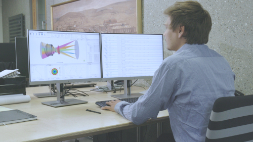


Global and Local Coordinate Systems in QUADOA® Optical CAD
In QUADOA® Optical CAD, every assembly has a local coordinate system: the elements inside it are positioned relative to that assembly, while the assembly itself is positioned in the global coordinate system of the whole system. Moving an element changes its position within the assembly; moving the assembly moves everything inside it in the global coordinate system. The example is a Linnik interferometer from the examples folder.
Key points
- The global coordinate system is the reference of the whole optical system.
- An assembly is positioned in the global coordinate system (or in the coordinate system of its parent assembly).
- Elements inside an assembly are positioned in the local coordinate system of that assembly.
- Moving an element moves it within the assembly; moving the assembly moves all its elements.
Terms used in this article
- Global coordinate system
- The coordinate system of the whole optical system.
- Local coordinate system
- The coordinate system of an assembly, to which the positions of its elements refer.
- Parent assembly
- The assembly that contains an element or another assembly.
Example: Linnik interferometer
In the Linnik interferometer from the examples folder, one assembly contains five lenses. The assembly is moved by 20 mm in Z. These 20 mm refer to the global coordinate system of the whole system.
The five lenses inside the assembly have their own positions. These refer to the local coordinate system of the parent assembly, not to the global coordinate system.
How do global and local coordinate systems relate?
| Object | Position refers to | Effect of moving it |
|---|---|---|
| Assembly | Global coordinate system | The assembly and all its elements move |
| Element in the assembly | Local coordinate system of the parent assembly | Only this element moves, within the assembly |
The general rule: every physical object, such as a surface, lens, element or assembly, has its own local coordinate system, and its position is always defined in the local coordinate system of its parent. Only objects without a parent are positioned in the global coordinate system. Because assemblies can be nested, this works over any number of levels.
Axis convention
All coordinate systems in QUADOA® are right-handed: the Z axis (typically the optical axis) points to the right, the Y axis points up and the X axis points into the screen. Positive rotations follow the right-hand rule.
This hierarchy mirrors a real mechanical design, where lenses are mounted in a barrel and the barrel is mounted in the instrument. See also assemblies and absolute and relative positions.
Video tutorial: global and local coordinate systems
This 2-minute video explains global and local coordinate systems using a Linnik interferometer.
Video length: 1:32 min · Also on YouTube: Global and Local Coordinate Systems in QUADOA® Optical CAD
Frequently asked questions
The global coordinate system is the reference of the whole system. Elements inside an assembly are positioned in the local coordinate system of that assembly, which itself is positioned in the global coordinate system.
The lens moves within the local coordinate system of its assembly; the assembly and the other lenses stay in place.
The whole assembly, including all its elements, moves in the global coordinate system.
All coordinate systems are right-handed: Z points to the right along the optical axis, Y points up and X points into the screen.